
Blog

What Is DIN 42530 1/250 Transformer Bushing?

A Din 42530 1/250 Transformer Bushing is a compact but critical connection between a transformer’s internal winding and an external circuit. Its porcelain body provides insulation, while the central conductor carries current through the transformer tank wall. In this designation, “1/250” is commonly associated with a DIN 42530 form and a 250-ampere rating. However, markings can vary by manufacturer, so the product datasheet remains essential.

This component often appears simple. It is not.

Correct selection requires attention to voltage class, conductor dimensions, mounting arrangement, sealing surfaces, and creepage distance. A bushing may look suitable on a workshop bench, yet fail to match the transformer flange or cable lug. That small mismatch can cause overheating, oil leakage, or unsafe electrical stress. Experienced technicians inspect the porcelain for chips, hairline cracks, and contamination before installation. They also check terminal tightness and gasket condition, because mechanical details affect long-term insulation performance.

Reliable identification should combine the DIN designation, nameplate data, drawings, and the transformer manufacturer’s requirements. Do not rely on “250 A” alone. Temperature rise, continuous loading, short-circuit forces, and environmental exposure also matter. Field experience shows that storage conditions can influence installation quality; damp packaging and careless handling leave visible clues. Even careful references may be incomplete. Therefore, this guide treats the Din 42530 1/250 Transformer Bushing as a practical engineering subject, while recognizing that final approval belongs to qualified personnel and verified technical documentation.
What Is DIN 42530 1/250 Transformer Bushing?

DIN 42530 Scope: 1 kV Insulation Class and 250 A Rated Current

What Is DIN 42530 1/250 Transformer Bushing?

DIN 42530 1/250 generally describes a transformer bushing with a 1 kV insulation class and a 250 A rated current. The 1 kV value relates to the bushing’s insulation capability under defined test conditions. It should not be treated as a universal operating limit without reviewing the complete transformer design. Insulation coordination still matters.

The 250 A rating indicates the continuous current the bushing can carry under specified service conditions. Temperature, installation position, conductor size, and surrounding air movement can affect performance. A practical inspection should check the terminal dimensions, contact surfaces, creepage distance, and clearances before installation. Small errors matter.

The bushing must also match the transformer tank opening and sealing arrangement. Check the technical drawing, mounting hardware, gasket condition, and tightening torque. Loose connections may create hot spots. Excessive torque can damage ceramic or polymer parts. That assumption can fail.

From field experience, installers sometimes focus only on the 1/250 marking. This is incomplete. Short-circuit withstand, ambient temperature, altitude, and insulation testing require separate verification. A qualified engineer should compare the bushing data with the transformer’s rated voltage and current. Test records should be retained, even when the installation appears straightforward.

How Porcelain, Conductors, and Seals Form a 1/250 Bushing

What Is DIN 42530 1/250 Transformer Bushing?

A DIN 42530 1/250 transformer bushing provides a safe passage for a conductor through the tank wall. The designation commonly relates to a 1 kV class and 250 A current rating. Always verify the exact interpretation in the project documents. Standards and supplier drawings may use different marking practices.

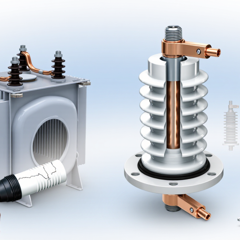
Porcelain forms the main insulating body. Its glazed surface resists moisture, dust, and surface tracking. Inside, a copper or aluminum conductor carries current between the external terminal and the transformer winding. Metal fittings hold the assembly firmly. Seals sit around the mounting area and conductor path. They help prevent oil leakage and moisture entry. A small seal defect can become a serious maintenance problem. The bushing may look perfect, yet internal aging can remain hidden.

Tips:Check the porcelain for cracks, chips, and unusual staining. Confirm the conductor material, current rating, creepage distance, and mounting dimensions before installation. Tighten connections evenly, without forcing the ceramic body. Inspect gaskets after transport, because vibration can disturb seating. The label alone is not enough. I would also compare the drawing, test records, and actual dimensions. That extra check feels slow, but it often prevents a costly mismatch.

Key Dimensions, Creepage Distance, and Terminal Arrangement

DIN 42530 1/250 transformer bushing is generally understood as a low-voltage porcelain bushing rated at 1 kV and 250 A. The “1” indicates voltage class, while “250” indicates continuous current capacity. Exact dimensions depend on the applicable drawing revision. Typical checks include overall length, flange diameter, mounting-hole pattern, conductor opening, and sealing-gasket position. A few millimetres matter here. Poor alignment can place mechanical stress on the porcelain.

Creepage distance is the surface path between the energized terminal and the grounded mounting flange. DIN 42530 provides a defined geometry, but field performance also depends on moisture, dust, and salt deposits. IEC 60815-1 links creepage selection to site pollution severity, rather than using one universal distance. CIGRE Technical Brochure 642 also identifies external insulation and bushings as recurring transformer reliability concerns. That finding is practical, not theoretical. Clean porcelain can still fail under sustained wet contamination.

The terminal arrangement normally separates the internal conductor connection from the external cable or busbar connection. Many assemblies use an internal threaded stud and an external bolted terminal, but this must be confirmed against the supplier drawing. Check thread size, tightening access, conductor clearance, and terminal orientation before installation. IEC 60137 testing principles also emphasize electrical clearances, temperature rise, and dielectric withstand. One overlooked detail remains common: a correct current rating does not guarantee correct creepage performance. Reference: DIN 42530, IEC 60137, IEC 60815-1, and CIGRE Technical Brochure 642.

What Is DIN 42530 1/250 Transformer Bushing? - Key Dimensions, Creepage Distance, and Terminal Arrangement
Category Parameter Reference Value Unit Technical Description
Electrical Classification
Designation DIN 42530 1/250 1 / 250 — The designation commonly identifies a transformer bushing for the 1 kV class and a continuous current rating of 250 A.
Rated voltage Insulation system rating 1.0 kV Nominal rated voltage associated with the 1 kV DIN 42530 bushing class.
Rated current Continuous current 250 A Continuous current rating under the applicable installation, temperature-rise, and conductor-size conditions.
System frequency Power frequency 50 / 60 Hz Suitable for standard utility and industrial AC transformer systems at either 50 Hz or 60 Hz.
Insulating medium Transformer-side insulation Transformer oil — The inner portion is intended to pass through the transformer tank wall and operate with the transformer insulating medium.
Insulation and Creepage
External creepage distance Surface leakage path Approximately 45 mm Typical reference value for the compact 1 kV / 250 A porcelain bushing configuration; the approved drawing should be used for final verification.
External arcing distance Shortest air path Approximately 35–40 mm Typical air distance between the external live terminal and the grounded flange or mounting surface.
Insulator material Outdoor insulating body Glazed electrical porcelain — Porcelain provides mechanical support, electrical insulation, and a weather-resistant glazed surface.
Surface profile Insulating sheds Profiled porcelain — The external profile increases the leakage path compared with a smooth cylindrical insulator.
Mechanical Dimensions
Overall installed length Typical bushing envelope Approximately 210–220 mm Typical overall length from the external terminal end to the transformer-side conductor end; actual length depends on the approved mechanical drawing.
Mounting flange diameter Tank-side flange Approximately 100 mm Typical circular flange size used for mounting the bushing to a transformer tank cover or wall.
Mounting-hole pattern Flange fixing 4 × Ø11 on approximately Ø80 mm Typical four-hole arrangement; hole-circle diameter and hole size must be matched to the transformer tank fabrication drawing.
Tank cut-out Required installation opening Approximately Ø70–75 mm Typical clearance range for the bushing body through the tank wall, excluding the flange fixing holes.
Conductor passage Internal current path Approximately Ø24 mm Typical passage size for the internal conductor or connecting rod in a 250 A arrangement.
Terminal Arrangement
External terminal Air-side connection Threaded stud, typically M12 — Used for connection to a cable lug, busbar, or transformer lead. The terminal should be tightened with the specified torque.
Internal terminal Transformer-side connection Axial conductor connection — The internal end normally connects directly to the transformer winding lead or an internal flexible conductor.
Terminal alignment Conductor axis Straight-through, axial — The external and internal electrical connections are arranged along the same central axis through the porcelain body.
Connection hardware External fixing accessories Nut, washer, and cable-lug interface — Hardware should be selected for the conductor size, current rating, corrosion environment, and applicable electrical-clearance requirements.
Installation and Verification
Mounting position Transformer installation Vertical or approved angled mounting — Installation orientation must follow the transformer design and the bushing manufacturer's approved drawing.
Flange sealing Tank interface Oil-resistant gasket required — The gasket must provide a leak-tight seal and be compatible with the transformer insulating oil and operating temperature.
Clearance check External live-part clearance Verify against installation voltage — Air clearance to the tank, adjacent phases, cable screens, and grounded metalwork must be checked during equipment design.
Dimensional control Final manufacturing reference Approved component drawing — DIN 42530 identifies the bushing application and principal rating; exact mechanical dimensions, tolerances, and terminal details should be confirmed from the controlled drawing for the selected configuration.
Reference note: The values marked as approximate represent a typical DIN 42530 1/250 transformer-bushing configuration. Final creepage distance, flange geometry, mounting-hole pattern, tolerances, terminal thread, and insulation-test levels should be verified against the applicable standard edition and the approved technical drawing.

Electrical Tests: Power-Frequency Withstand and Insulation Resistance

What Is DIN 42530 1/250 Transformer Bushing?

A DIN 42530 1/250 transformer bushing is an insulated passage for connecting an internal winding to an external conductor. The designation refers to a standardized bushing configuration, while exact voltage, current, and mounting details require confirmation from the nameplate or technical drawing. Its insulation must remain stable under electrical stress, moisture, contamination, and temperature changes.

The power-frequency withstand test checks whether the bushing tolerates an AC voltage at the specified test level and duration. Technicians first inspect the surface, clean the insulation, and confirm proper grounding. During testing, there should be no flashover, puncture, or abnormal discharge.

Insulation resistance is then measured with a suitable megohmmeter. Readings should be recorded with test voltage, temperature, humidity, and connection details. A high value is encouraging, but it does not prove perfect insulation.

Surface leakage can distort results, especially in damp conditions. One reading is never enough.

Tips: Keep the bushing dry and dust-free before testing. Follow the applicable DIN requirements and the transformer manufacturer’s procedure. Compare each phase with the others and with previous records. Large differences deserve investigation, even when values exceed the minimum limit. After testing, discharge the bushing safely; stored electrical energy can remain briefly. Testers should use calibrated instruments and verified isolation. Small procedural errors matter.

Selecting a DIN 42530 1/250 Bushing for Distribution Transformers

A DIN 42530 1/250 transformer bushing is an insulated passage for carrying a conductor through a transformer tank wall. The designation usually identifies a DIN-based design with a 250 A current class. It provides electrical insulation, mechanical support, and a sealed connection point. In distribution transformers, the bushing must withstand oil, heat, vibration, and outdoor exposure.

Selecting a DIN 42530 1/250 bushing requires more than matching the current rating. Check the transformer’s rated voltage, insulation level, creepage distance, and terminal arrangement. Confirm the tank opening, flange dimensions, fixing-hole pattern, and conductor connection. A 250 A rating may be suitable for a compact distribution transformer, but continuous loading and ambient temperature can reduce the practical margin. Measure twice.

Field installation also deserves attention. The porcelain or composite body should arrive without chips, cracks, or surface contamination. Gaskets need even compression, not excessive tightening. Poor alignment can create mechanical stress around the flange. I have seen installation teams focus on electrical data while overlooking the available clearance above the tank. That mistake can complicate cable routing and maintenance.

Before ordering, compare the bushing drawing with the transformer’s actual interface. Verify phase-to-ground clearance, neutral requirements, sealing materials, and test documentation. It is also wise to confirm the applicable DIN edition and the manufacturer’s routine-test results. Specifications can look complete yet miss one critical dimension. A careful review prevents costly field modification.

Selection guide: A DIN 42530 1/250 bushing is commonly associated with a 1 kV class and a nominal 250 A current rating. The chart compares calculated full-load current for typical three-phase transformer ratings at 400 V. Transformers above approximately 160 kVA can exceed 250 A at full load, so voltage, load current, connection system, thermal conditions, and applicable technical documentation should be verified before selection.
Go to Top